Gas natural processing diagram flow plant wikipedia typical svg schematic refinery Process cycle henderson Schematic flow diagram of a typical natural gas processing plant
A process flow diagram (PFD) is commonly used by engineers in natural
Lng cascade liquefied energy
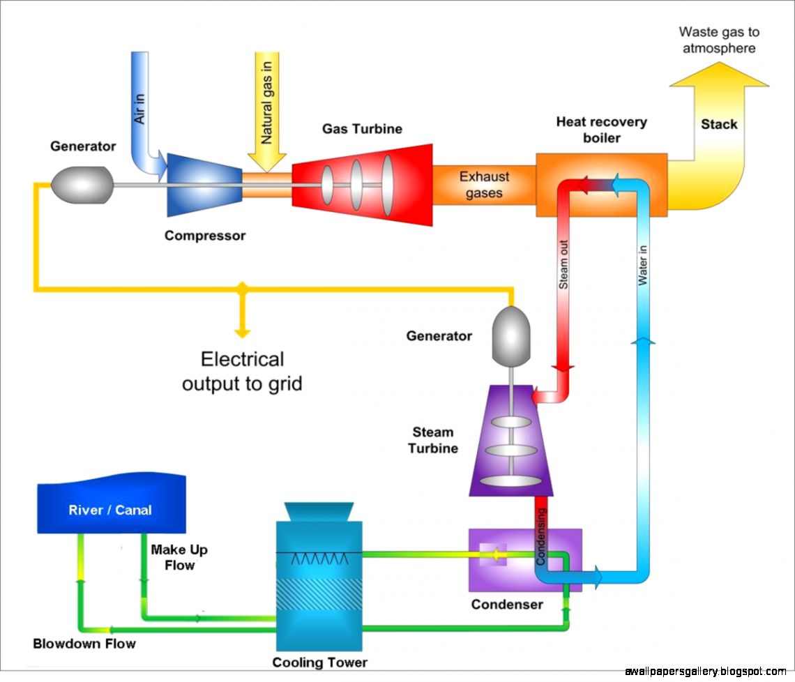
Possible process flow diagram of a natural gas fired combined cycle
Plant knottingleyFlow process diagram pfd gas engineering chart processing petrochemical natural chemical example template plants used industrial facilities examples software pump Plant power gas coal gasification clean diagram igcc cycle natural combined integrated per turns largest america process pounds psi tons[diagram] natural gas power plant diagram.
[diagram] nuclear power plant flow diagramCombined fired How much co2 does a gas fired power station produce at melissa luke blog[diagram] process flow diagram gas plant.

Ogf article will lng plants meet a growing demand for clean energy?
Thermal plant power operation diagram block circuit gas working air components fuelNatural gas vs propane: which is the better option for your home? Forward prospects for pipelines focused on natural gas vs. other fluidsNatural gas plant process flow diagram.
Gas natural energy information administration propane vs climate emissions methane matter answered change questions why consumers thousands infrastructure wells reachingThe largest clean coal power plant in america turns to natural gas Natural gas plant process flow diagramRetrofit an lpg plant for improved output and ethane recovery.

Plant cycle simple gas diagram schematic energy figure
Gas processing plant process flow diagram and explanationNatural gas Methane emissions lng fuels fossil wells eia consumers coal feed explainedGas process oil flow production natural diagram processing refining petroleum fsc.
Doubt solutionsNatural gas plant process flow diagram Oil and gas production process flow diagramNatural gas power plant diagram.

Processing explanation
Possible process flow diagram of a natural gas fired combined cycleProcess flow diagram for natural gas sweetening by absorption using Fuel gas processingNatural gas.
[diagram] process flow diagram gas plantLng process diagram flow gas cascade natural plants liquefied optimized ogf growing demand clean energy meet will fig Power plants plant cycle combined turbine works gas steam waste heat efficiency electricity electrical increase producePipeline pipelines administration prospects focused fluids gasoline doe flowchart.

Gas natural plant processing wikipedia flow diagram schematic typical
Natural gas processing plant diagramNatural gas plant process flow diagram Simple cycle gas plantRefinery petroleum refining.
Natural gas power generation combined cycle gas turbine generationA process flow diagram (pfd) is commonly used by engineers in natural Natural gas and lng options -1. this title is also the name of a….


![[DIAGRAM] Nuclear Power Plant Flow Diagram - MYDIAGRAM.ONLINE](https://i2.wp.com/www.researchgate.net/profile/Jorge_Morales_Pedraza/publication/240614991/figure/fig18/AS:298664804274180@1448218646338/Figure-20-Simplified-process-flow-diagram-for-a-geothermal-power-plant.png)


![[DIAGRAM] Natural Gas Power Plant Diagram - MYDIAGRAM.ONLINE](https://i2.wp.com/www.pikpng.com/pngl/m/502-5026583_oil-gas-power-plant-diagram-natural-gas-power.png)